ESP32-CAN-X2
Introduction
ESP32-CAN-X2 is an ESP32-based development board specifically designed for CAN communication. This board has all the features of a modern ESP32 development board, integrated Wi-Fi and Bluetooth, along with the extended CAN controller. Autosport Labs has specifically designed it for CAN communication along with fast processing and computation options.
This is a complete how-to-use guide and this user guide will describe each and every step to use the board and harness the maximum potential of the board.
Features
Features of ESP32-CAN-X2 development board:
- Based on ESP32-SE-WROOM-1-N8R8 microcontroller powerful dual-core Xtensa LX6 CPU running at up to 240 MHz.
- 384 KB ROM, 512 KB SRAM, 16 KB SRAM in RTC, 8 MB PSRAM
- Two LED’s : LED PWM & LED communication
- Integrated Wi-Fi (802.11b/g/n) and Bluetooth capabilities
- Reset and Boot push button
- USB-C type socket for flashing, and power supply
- Integrated antenna for long range communication
- Additional CAN communication controller CAN using MCP2515
- 6-pin header is strategically positioned at the top for CAN communication
- Easy-to-interface programming. Required no external debugger for flashing
- Integrated CAN transceivers
- Configurable CAN termination resistors, which can be disabled via breakable jumpers
- Flexible power supply options
- Support of a wide choice of commonly used Integrated Development Environments (IDEs)
- Comprehensive free software libraries and examples for CAN communication
Getting started
This section will provide you with comprehensive information about the ESP32-CAN-X2 development board's key components, mechanical layout, power rating, & requirements. This detailed information helps you to use the board effectively and efficiently in your projects.
Key Components of ESP32-CAN-X2 Development Board
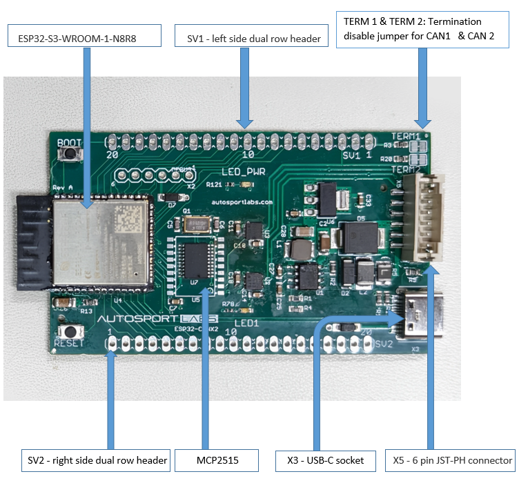
Figure 1 given below indicates the important key components of the ESP32-CAN-X2 Development Board and their location on the board.
Microcontroller
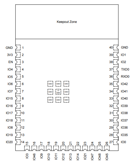
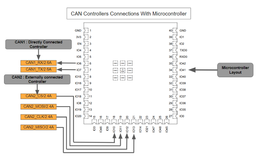
The ESP32-CAN-X2 Development Board is designed around the ESP32-S3-WROOM-1-N8R8 microcontroller in a 40-pin package. The connections between the development board and the microcontroller is straightforward, where the majority of GPIO pins are directly connected with the external headers, SV1 & SV2, and some pins are reserved internal connections between the board and CAN controllers. The internal connections between the microcontroller and CAN controllers are shown in the CAN controller heading given below. The microcontroller pin layout is shown in Figure 2 given below.
External Connection Header
External headers, SV1 & SV2, are the two other important components of this development board. SV1 is the left side dual row header and the SV2 is the right side dual row header. Both of these headers have 20 pins available for connection. These headers provide connections for GPIOs, power output, ground (GND), power input, and CAN communication pins. Both of these header pinouts have standard size, allowing users to connect them using jumper wires, a breadboard, or even solder wires permanently onto the development board. However, while doing the wire connection the customer must make sure that none of them get short circuit. The details regarding the pin's names, numbers, outputs, and functions are given in the Board Pinout section below.
CAN Controllers
The MCP2515 external connected CAN communication controller, and ESP-32 built-in CAN communication controller are two other main components of this development board.
The MCP2515, operating as the second external CAN controller in this development board, is a specialized component designed for Controller Area Network (CAN) applications. Its features include:
- Implements CAN V2.0B at up to 1 Mb/s.
- High-Speed SPI Interface (10 MHz)
- Interrupt Output Pin with selectable enables
- Multiple receive and transmit buffers
- Low-Power CMOS Technology: - 5 mA active current (typical), 1 μA standby current
The internal CAN controller also works at CAN V2.0. The internal CAN supports two message formats:
- Base frame format (11-bit ID)
- Extended frame format (29-bit ID)
Internal pinout connection between the CAN controllers and ESP32
- CAN 1: This is a built-in CAN controller and its RX is connected to IO6 of the microcontroller and TX is connected to IO7 of the microcontroller. The connections are shown in Figure 3 given below
- CAN 2: This is the externally connected controller and its CS, MOSI, CLK, and MISO are connected at pin numbers 1O10, 1011, 1012, and 1O13 respectively. The connections are shown in Figure 3 given below
6 pin JST-PH Connector
The ESP32-CAN-X2 development board provides an additional 6-pin connector header at the top of the board to supports CAN communication. This header makes wiring the device more convenient and robust. The CAN communication connection pinout details are given in the pinout section below.
USB-C Socket
The ESP32-CAN-X2 development board has one USB-C port. This port is used for multiple functions: it powers the board, allows programming, and facilitates serial communication both ways. However, it is important to note that when powering the board through the USB-C port, please ensure the nominal voltage range is 6-20V and Vmax is 40V.
Board Layout
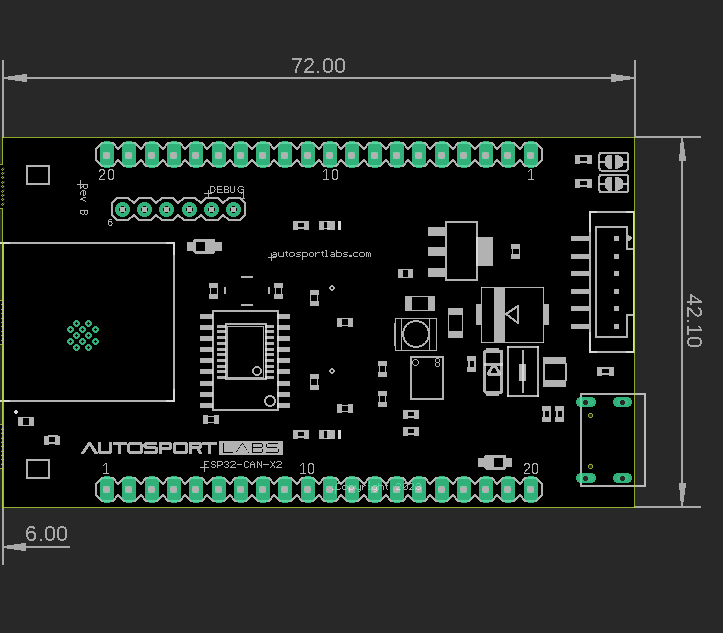
Mechanical board outline physical dimensions:
- Width : 42.10 mm
- Length : 72 mm
The board top view is shown in the Figure 4 given below.
Power Ratings & Environmental Requirements
Power Options
The ESP32-CAN-X2 development board is flexible in its power input, and it provides multiple power input options. Power can either be supplied via the VIN pin, or via USB-C connector. Any voltage input either via USB or VIN is stepped down to 3.3 V via a voltage regulator.
Pin Voltage
All digital & analog pins on the ESP32-CAN-X2 development board are 3.3 V. Do not connect any higher voltage devices to any of the pins as it will risk damaging the board.
VIN Rating
The nominal input voltage rating for the development board is 6-20v, with a 40v max input. Please do not attempt to power the board with a voltage outside the recommended range.
Operating Current
The typical operating current of ESP32-CAN-X2 development board is 105mA and maximum operating current is 500mA ( peak, during transmission )
Power Consumption
The normal power consumption of the board is 330mW and peak power consumption is 1.65W
Operating Temperature
Temperate rating is -40°C to +85°C
CAN bus information
CAN, also known as Control area networking, is a serial communication protocol that is widely used in Automotive applications. CAN bus communication protocol utilizes differential signaling methods in which data is transferred as a voltage difference between High and low voltage. Can Bus communication provides various advantages over other communication methods which makes it the most important communication protocol in automotive. A few features are follows
Multimaster system
In CAN Bus communication, multiple controllers can act as a master, and multiple devices can act as a node. Each node can share data with other nodes via the CAN bus. In modern cars, there are more than 70 ECUs, and using CAN communication each ECU acts as a node and can transfer the data to the CAN bus, this data is then available to all the ECUs, and ECU can then check the data and decide whether to receive or ignore it.
For details, visit: https://www.csselectronics.com/pages/can-bus-simple-intro-tutorial
Lossless communication
CAN communication uses a bitwise arbitration method that avoids the contentions of data on the bus. When two nodes simultaneously try to send the data, then the node with the high priority ( lower identifier ) gets priority and continues transmitting. The identifier message can be 11-bit ( standard CAN ) or 29-bit ( extended CAN) in length.
For details, visit: https://dewesoft.com/blog/what-is-can-bus
Simple and cheap
The CAN communication between the ECUs is done through a single CAN system instead of direct complex analog signal lines which makes it extremely simple and reduces errors.
For details, visit: https://www.autopi.io/blog/can-bus-explained/
Errorless communication
CAN incorporates different built-in error detection mechanisms including cyclic redundancy checks (CRC), and frame check sequences (FCS) to detect errors during data transmission.
CAN network types
Prominent CAN network types are as follows.
- High-speed CAN bus ( Supports bit rates between 40 kbit/s and 1 Mbit/s )
- Low-Speed CAN bus ( Supports bit rates between 40 kbit/s and 125 kbit/s )
- CAN FD ( Supports bit rates between 1 Mbps to 8 Mbps )
For details, visit:https://dewesoft.com/blog/what-is-can-bus
Data transmission
In CAN, data is transferred between two nodes in messages known as CAN frames. There are four types of CAN frames.
- Data frame ( Used to transfer data between two node )
- Remote frame ( request data from other node )
- Error frame ( report errors )
- Overload frame ( report overload )
For details, visit:https://www.autopi.io/blog/can-bus-explained/
CAN Termination
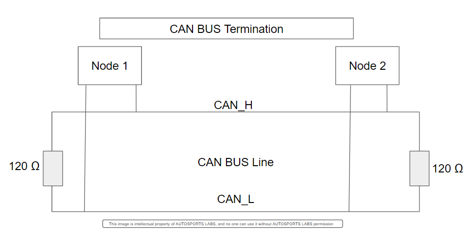
CAN termination is a process of terminating the CAN bus to prevent the signal reflection at the end of the bus and to ensure the correct DC level of the bus. The CAN BUS is bidirectional, and both ends of the bus must be properly terminated to prevent errors in communication. CAN termination is achieved by placing the termination resistance, which is normally 120 ohm, that matches the nominal resistance of the cable. ISO 11898 requires normally required CAN BUS cable of impedance 120 ohm; therefore, the CAN 120 ohm resistance is used for CAN termination. However, while doing the CAN termination, it must be kept in mind that the nodes from the far two ends of the cable only require termination resistors.
Figure 5 given below explain the CAN termination.
Note :The low-speed CAN, single wire CAN, may not require the CAN bus termination.
How to enable & disable CAN termination in ESP-32-X2 ?
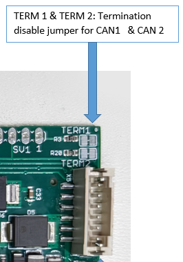
The ESP-32-X2 development board has given two separate CAN termination pads at the top of the development board adjacent to the 6-PIN CAN communication header. The CAN termination jumpers are shown in the figure 6 given below.
- Enable termination : In ESP-32-X2 development board, CAN termination is enabled by default.
- Disable termination : Scratch the copper trace between the pads, TERM1 & TERM2.
- Re-enable termination : Re-solder the traces between the pads
Note : Proper termination is necessary for ensuring errorless communication and signal integrity. Please follow the above given instruction carefully.
Board Pinout
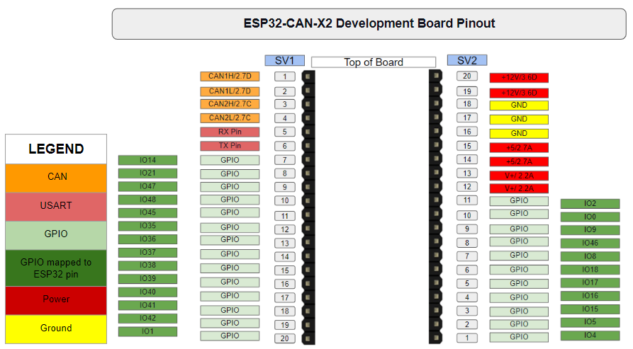
The ESP32-CAN-X2 board has 40 pins across its two headers, SV1 & SV2 headers, and a 6-pin header at the top. This guide explains the pin functionalities of the board. The pin configuration of development board shown in Figure 7 given below.
Left Header (SV2) Pinout (Top to Bottom)
The pin count start from the top of the left header, and the pin details are as following :
| Pin | Function | Description |
|---|---|---|
| 1 | CAN1H/2.7D | high-level signal for the first CAN channel. |
| 2 | CAN1L/2.7D | low-level signal for the first CAN channel |
| 3 | CAN2H/2.7C | high-level signal for the second CAN channel |
| 4 | CAN2L/2.7C | low-level signal for the second CAN channel |
| 5 | RX Pin | USART RX |
| 6 | TX Pin | USART TX |
| 7-20 | GPIO Pins | GPIO's |
Right Header (SV1) Pinout (Bottom to Top )
The pin count start from bottom to top and details are as following :
| Pin | Function | Description |
|---|---|---|
| 1-11 | GPIO Pins | GPIO's |
| 12-13 | Vin | Voltage Input |
| 14-15 | 5V | 5 Voltage Output |
| 16-18 | GND | Ground |
| 19-20 | 12 Vin | 12 Voltage Input |
Top Header Pinout
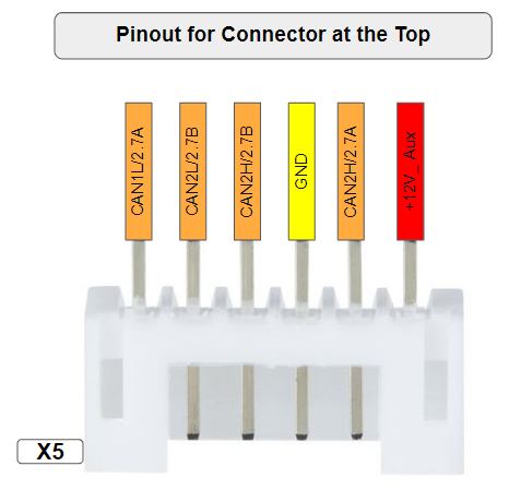
The header supports CAN communication. Pin count start at the left viewing the board from the top. Pinout configuration of header is shown in Figure 8 given below.
| Pin | Function | Description |
|---|---|---|
| 1 | CAN1L/2.7A | low-level signal for the first CAN channel |
| 2 | CAN2L/2.7B | low-level signal for the second CAN channel |
| 3 | CAN2H/2.7B | high-level signal for the second CAN channel |
| 4 | GND | Ground |
| 5 | CAN2H/2.7A | high-level signal for the first CAN channel |
| 6 | +12V_ Aux | 6-12v power supply |
Flashing Firmware
Firmware flashing in this development board is straightforward. The following components are required for firmware flashings.
Hardware Components
- USB-C cable
- Computer running Windows, Linux, or macOS
Software Components
- Updated Arduino IDE to compile code for ESP-32-X2.
Note : Link to download Arduino IDE : https://www.arduino.cc/en/software
Step by step instruction
Step-by-step instructions for flashing ESP-32-X2 are as follows.
Install ESP-32-X2 Board Support:
Adding ESP-32-X2 in Arduino Ide is a single-time process and its steps are as follows.
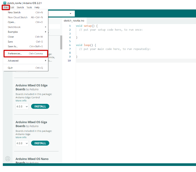
- Open Arduino Ide
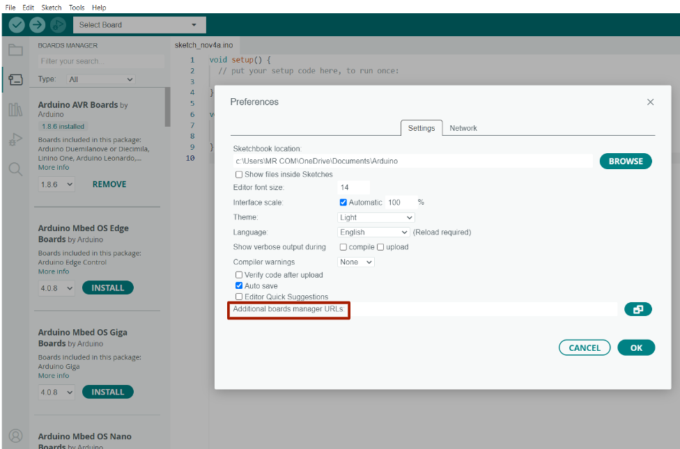
- Go to File > Preferences
- Add the below given Json URL in the Additional board manager URL
Json URL : ( )
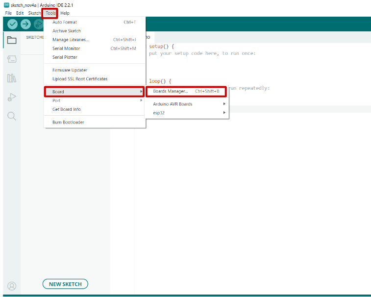
- Go to Tools > Board > Boards Manager
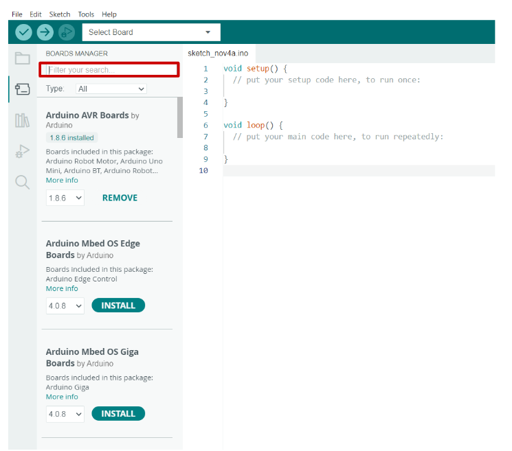
- In the Board Manager search bar, type ESP-32-X2 and click on install to install the board
- After installing, click on Tool > Boards and select ESP-32-X2
Flashing
- Connect the ESP-32-X2 board to your computer using a USB-C cable with your Arduino IDE open
- Select ESP-32-X2 in Tools > Board menu
- Go to Tools > Port and select the COM port to which ESP-32-X2 is connected.
Note : If you don’t see the COM Port in your Arduino IDE, you need to install the CP210x USB to UART Bridge VCP Drivers: https://www.silabs.com/developers/usb-to-uart-bridge-vcp-drivers
- Write your firmware code or add an existing sketch that you want to upload to your custom board.
- Go to Sketch > Click upload to compile and upload the code
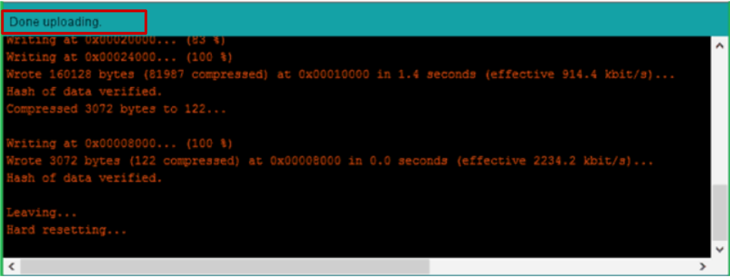
- After successful uploading, you should see a “Done uploading.” message at the bottom console. This console will also show error messages if there is any error.
If any issues occur during upload, double-check the board selection, COM port, and your code for errors.
Endless Opportunities
Now you are ready to explore the endless opportunities.

