RaceCapturePro SoftwareOperation
First time use
Installing the RaceCapture/Pro drivers
When connected to the computer over USB, RaceCapture/Pro appears as a virtual serial port.
- Windows users will need the proper drivers installed. Download the drivers and unzip them to a directory. When you connect RaceCapture/Pro to your computer using the USB cable Windows will prompt you to install drivers- specify the directory where you downloaded the files.
Windows 8 Note
Windows 8 insists on signed drivers; the RaceCapture/Pro drivers are not signed and Windows 8 by default requires signed drivers. To bypass this requirement, follow these instructions
Installing RaceAnalyzer
Download the version of RaceAnalyzer that matches the firmware in your RaceCapture/Pro. firmware. If unsure, just try using the latest version.
Minimum System Requirements
- Windows XP or later
- Pentium IV 1GHz
- 1GB RAM
- 10 MB Disk space
Setting the Serial Port
Run RaceAnalyzer by finding the icon under the Start Menu program group. Once the program is running, you can set the serial port the RaceCapture/Pro is connected to by clicking Tools/Configurator Options.
<<screenshot of Tools / Configurator Options>>
- To find out what COM port Windows assigned to RaceCapture/Pro, open Device Manger by finding 'My Computer', right-click and select Properties. From this window you will be able to access Device Manager.
Expand the 'Ports (COM & LPT)' to see the list of installed COM ports.
 <<Replace this with screenshot of RaceCapture/Pro listed under COM ports>>
Once you're certain which COM port was assigned to RaceCapture/Pro, select this value in the options dialog.
Configuration Perspective
The configuration perspective allows you to read and write the RaceCapture/Pro configuration settings.
To enable this perspective, click the wrench icon in the RaceAnalyzer toolbar.
Reading Configuration
To Read the current RaceCapture/Pro configuration connect the RaceCapture/Pro unit to the computer over USB and then click the "Read" button at the bottom of the window.
GPS Configuration

GPS Installed
Check this if the GPS unit is installed on RaceCapture/Pro.
Start/Finish Line
RaceCapture/Pro can track Lap Counts, Lap times and Split Times by specifying a target on the earth using GPS coordinates.
To set either the Start/Finish or Split time target specify the latitude, longitude and target radius in the Start/Finish Line section.
- PROTIP: You can fetch the start/finish line GPS coordinates using Google Maps
- Instructions
- Search for the race track
- Go to Maximum Zoom on the start/finish line
- Right click the start finish line and select "What's Here"
- The GPS coordinates will be shown. Enter these values into the Start Finish line coordinates.
- Example Start Finish coordinates for Laguna Seca Raceway
The GPS target is defined as a circle with a radius. Currently this radius is in degrees of latitude/longitude. We currently recommend a value between 0.0001 and .0005 degrees, which is about 30 to 60 feet radius, depending on the latitude of the target
Split Time Line
Find a spot roughly 1/2 way around the track and find the GPS coordinates for that location. Enter these values into the Split Time fields.
GPS Channels
| Channel | Description |
|---|---|
| Latitude/Longitude | Position on the earth. It's recommended you specify the same sample rates for both channels. |
| Speed | This is ground speed in MPH as measured by the GPS module. |
| Time | Time of day, expressed as seconds since midnight. |
| GpsSats | The number of GPS satellites in view - an indicator of GPS signal quality. Usually this channel will be disabled. |
| LapCount | The number of laps detected by RaceCapture/Pro since the start of the datalogging session. The Start/Finish Line target configuration must be set to use this feature. We recommend a sample rate of 1Hz on this channel. |
| LapTime | Indicates last lap time. This also requires a configured Start/Finish line target, and also 1Hz on the sample rate. |
| SplitTime | Indicates the last calculated split time, which is the time elapsed between the Start/Finish line and the Split Time |
Analog Inputs
RaceCapture supports 7 0-5v analog sensor inputs, and 1 internal analog input (channel 8) dedicated to measuring battery voltage.
Each channel can be set with channel name, units, sample rate and a way to configure how the sensor is scaled to a real world value.

Channel Name
Select channel name for your analog input from the drop down list, or you can specify your own channel name up to a maximum of 10 characters.
- We recommend selecting from the standard list of channel names when possible to be most compatible with the current and future features of RaceAnalyzer and related software.
Units
Optionally specify the units for your channel, such as Degrees, PSI, Volts, etc.
Sample Rate
Select the sample rate for the specified channel. You can select any combination of sample rates for the channels you enable.
Logging Precision
This configures the precision of the values written to the log file. The default logging precision is usually a good starting point.
Advanced Settings
The advanced analog settings allows you to map the raw value read by the sensor to a meaningful, real-world value that will be written to your log files.

To configure the scaling click the Advanced [...] button for the channel you're working with. You will be presented with 3 options:
- Raw Value
This writes the raw value read from the analog-digital converter (ADC) right to the log file, without any processing.
- Simple Linear Scaling
This applies a linear scaling multiplier to the 0-1023 raw value read from the analog input. The default scaling of 0.0049 provides a 0-5V value that will be written to the log file.
For example: 512 raw value * 0.0049 scaling = 2.5V
- Mapped Value
This option allows you to create a 5 point map to describe a non-linear sensor curve. Linear interpolation is performed between the points on the map to provide smooth conversion across the range.
You can use this option to log real world values from devices such as temperature sensors, fuel level senders, oil pressure sensor, and more.
Configure the Scaling Map by editing the values in the table above the graph.
- The row labeled Raw in the table represents the value read from the analog input port. By default, the points are equally distributed across the range, but you can change the values to change the shape of your curve.
- The row labeled Scaled in the table represents the value RaceCapture will map for the corresponding raw value. You can specify a positive or negative floating point number here.
Pulse Inputs
RaceCapture/Pro supports 3 pulse input channels which can be used to measure RPM, wheel speed, injector pulse widths, and other signals which produce a square wave or periodic pulses.

Channel Name
Select channel name for your pulse/timer input from the drop down list, or you can specify your own channel name up to a maximum of 10 characters.
- We recommend selecting from the standard list of channel names when possible to be most compatible with the current and future features of RaceAnalyzer and related software.
Units
Optionally specify the units for your channel, such as RPM, MPH, etc.
Sample Rate
Select the sample rate for the specified channel. You can select any combination of sample rates for the channels you enable.
Logging Precision
This configures the precision of the values written to the log file. The default logging precision is usually a good starting point.
Advanced Settings
The advanced settings allow you configure the way the pulse is logged- either in rate, like RPM, or in duration, like milliseconds. You can also configure additional options for further tuning the pulse input capabilities.
- Pulse Mode
Select the mode in which the logger should process the measured pulses. You can select RPM, Frequency, or pulse durations in either milliseconds or microseconds format.
- Timer Options
This setting configures the internal sampling rate for the timer that measures the input pulse. A smaller divider represents a faster sampling rate, which will allow measurements of faster pulse rates / higher frequencies. For most applications the default CLOCK / 128 should be used. Note: in the future this concept may change to sample rate measured in Hz
- Pulse Per Revolution
When measuring rotational speed, like RPM or wheel speed, you can specify the number of pulses generated for each rotation. For example: A wheel or shaft speed indicator may produce just one pulse per revolution; RPM measurement via cranshaft position or ignition pulse may produce 4 to 36 pulses per revolution.
Accelerometer Inputs
RaceCapture/Pro provides a high precision 3-axis accelerometer to measure vehicle dynamics plus yaw sensor to measure angular rotation suitable for measuring understeer and oversteer conditions. You can configure the channel mappings to accommodate various mounting positions as well as configure the neutral, zero value of the system after mounting.

Channel Name
Select the name of the accelerometer channel from the drop down list, or you can specify your own channel name up to a maximum of 10 characters.
- We recommend selecting from the standard list of channel names when possible to be most compatible with the current and future features of RaceAnalyzer and related software.
Units
Optionally specify the units for your channel- in this case, G (for G-force)
Sample Rate
Select the sample rate for the specified channel. You can select any combination of sample rates for the channels you enable.
Mode
You can invert the selected channel to allow for mounting upside down (Z and X axis inversion) and backwards (X axis inversion)
Mapping
You can map the physical accelerometer axis to the logged channel. For example: If RaceCapture/Pro was mounted vertically on edge, parallel with the length of the vehicle, you would:
- Map AccelX to the accelerometer Z axis
- Map AccelZ to the accelerometer X axis
- and AccelZ would remain mapped to the accelerometer Y axis.
Zero Value
You can manually change the neutral / zero value for the accelerometer and yaw channels.
Coming soon: The firmware has the ability to auto-calibrate the zero value; RaceAnalyzer will have a feature to do this automatically
Yaw Channel
For best results with the yaw sensor we recommend mounting RaceCapture/Pro flat (either right side up or down) and as near the center of the vehicle as possible. If mounted upside down, be sure to set the yaw channel's mode setting to 'inverted'.
<<todo: add graphic of RaceCapture/Pro orientation for accelerometer channels>>
Analog/Pulse Outputs
RaceCapture/Pro has 4 configurable analog or pulse output channels that can be logged along with other channels.

Channel Name
Select channel name for your analog/pulse output from the drop down list, or you can specify your own channel name up to a maximum of 10 characters.
Units
Optionally specify the units for your channel, such as Hz, Ms, etc.
Sample Rate
Select the sample rate for the specified channel. You can select any combination of sample rates for the channels you enable.
Logging Precision
This configures the precision of the values written to the log file. The default logging precision is usually a good starting point.
Mode
Specify if this channel is configured as an analog or digital output. You will also need to set the appropriate dip switch within the RaceCapture/Pro unit. See the Hardware Configuration Information page for how to set this up.
Advanced
The advanced settings let you configure the default behaviors when RaceCapture/Pro first powers up.
- Startup PWM duty cycle
Specifies the startup duty cycle % of the selected Pulse Width Modulated output
- Startup PWM period
Specifies the period of the selected Pulse Width Modulated output
- Voltage Scaling
Specifies the voltage scaling as related to the PWM %. Normally you would not need to change this value. For example: 50% PWM * 0.05 = 2.5V logged voltage
Digital I/O
RaceCapture/Pro has 3 configurable digital input/output channels.
- When configured as an input you can use it to detect the state of a switch-based sensor
- When configured as an output, you can drive loads up to 1A. See the Hardware Configuration page on how to set this up.

Channel Name
Select channel name for your analog/pulse output from the drop down list, or you can specify your own channel name up to a maximum of 10 characters.
Units
Optionally specify the units for your channel, if applicable.
Sample Rate
Select the sample rate for the specified channel. You can select any combination of sample rates for the channels you enable.
Logging Precision
This configures the precision of the values written to the log file. The default logging precision is usually a good starting point.
Mode
Specify if this channel is configured as an input or output. Make sure you configure the internal jumpers to match the selected mode - see the Hardware Configuration page on how to set this up.
Logging/Telemetry
Here you can specify the SD logging mode and define what device is attached to the connectivity expansion port.
- SD Logging Mode
Currently only CSV file output format is supported.
- Telmetry Mode
Settings to specify what type of device is attached to the connectivity expansion port, and related parameters.
This area is under development and will be undergoing changes as telemetry features are further developed
Scripting
RaceCapture/Pro supports automation of system behaviors using the lightweight Lua Scripting Language.

Use this editing window to read and write the Lua script you create. See the Lua Scripting information page for details on creating your own custom behaviors.
Analysis View
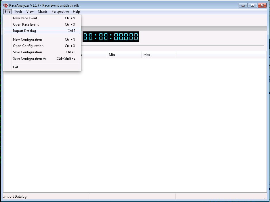
To analyze RaceCapture's logged data insert the sd card into a sd card reader and open RaceAnalyzer.
Step to analyze:
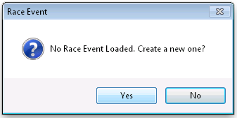
- Click File => Import Datalog
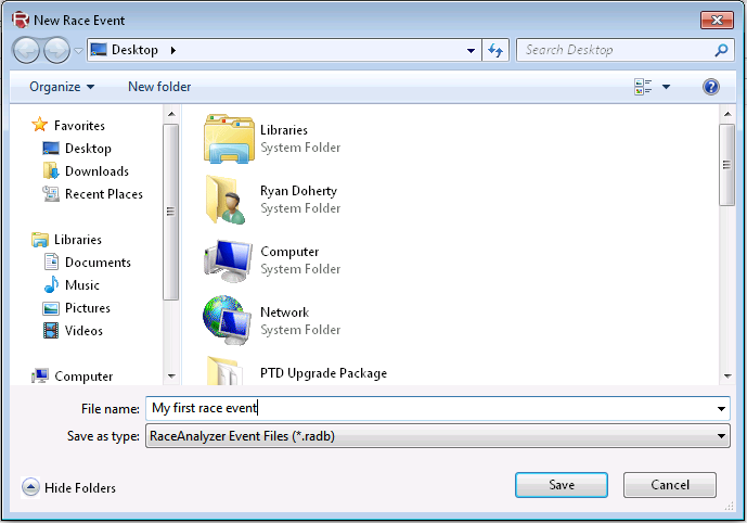
- Click Yes to 'No Race Event Loaded. Create a new one?'
- Name your race event and click Save
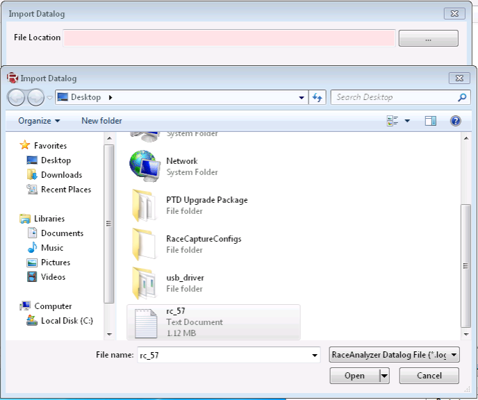
- When the Import Datalog screen appears, click on the '...' button on the right, select your datalog file and click Open
- Click Next to continue
- Enter the name for the datalog and a description if desired
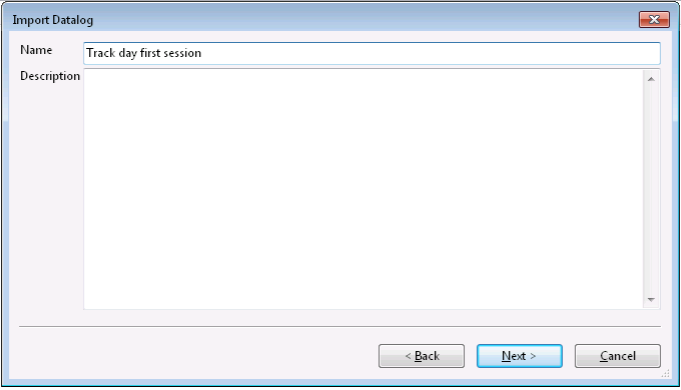
- Click Next
- Select the channels you wish to import (by default all will be imported, which is usually fine)
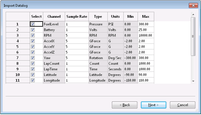
- Click Next
- Click Import
- Click Finish
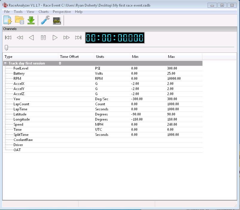
- Click the '+' next to the name of the datalog imported to view channels
- To create a chart from a channel, click on a channel, click Charts and select the chart type
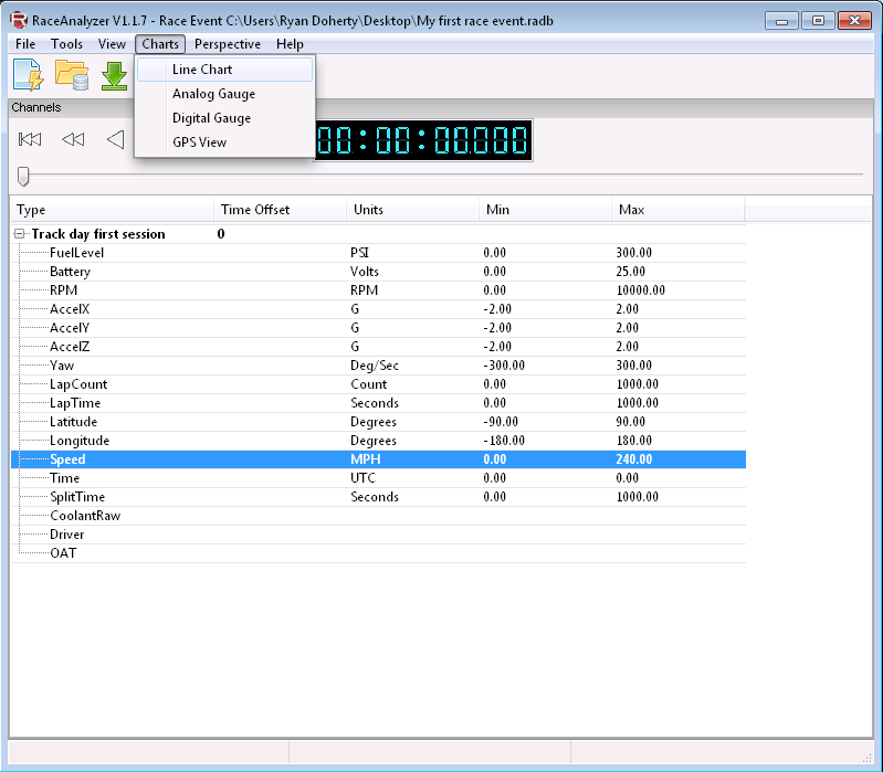
- Charts will appear at the bottom and are resizable and draggable.


Try creating a few different types to see what works for you. Playback controls are above the channel list. To create a map chart, select both Latitude and Longitude and select the GPS view from the Charts menu.