MJLJ V4 Operation Guide
First time use
Installing Configuration Software
Download the version of the Configuration software that matches your controller firmware. It's likely you have a very recent firmware image, so start by downloading the latest version of the Configuration Software from the Downloads section.
Minimum System Requirements
- Windows XP or later
- Pentium IV 1GHz
- 256MB RAM
- 10 MB Disk space
- Available serial port (built in or with compatible USB-Serial Adapter)
Setting the Serial Port
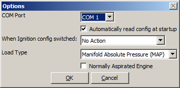
Find and run the Configuration software by finding the icon under the Start Menu program group. Once the program is running, you can set the serial port the MJLJ is connected to by clicking Tools/Configurator Options.
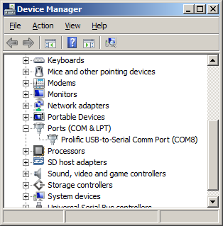
If you don't know which COM port you have the MJLJ connected to, you can discover this under Windows Device Manager: Find the 'My Computer' icon, right-click and select Properties. From this window you will be able to access Device Manager.
Expand the 'Ports (COM & LPT)' to see the list of installed COM ports.
Once you're certain which COM port you're using for the MJLJ, select this value in the options dialog.
USB-Serial Adapter
If your computer does not have an built-in serial port, see the USB-Serial adapter information page for help on selecting a compatible adapter.
Configuring MAP or TPS
In the Controller Options dialog, select the Load type you have for your MJLJ- Throttle Position sensor(TPS) or Manifold Absolute Pressure (MAP).
Configuring Normally Aspirated or Forced Induction
Check the 'Normally Aspirated' box if that matches your engine type. This setting will scale the load axis for the runtime and logging views to 103KPa maximum.
Otherwise, leave the box clear if your engine is turbocharged or supercharged. This will set the maximum scale to 255 KPa (approximately 21 PSI of boost)
Connecting to the MJLJ
Serial Cable (for older non-USB Megajolt systems)
The Megajolt Lite Jr uses an RJ11 jack for serial communications, located on the opposite side of the case from the molex connector.
You may construct a cable by modifying a 4 conductor modular phone cable per the wiring diagram:
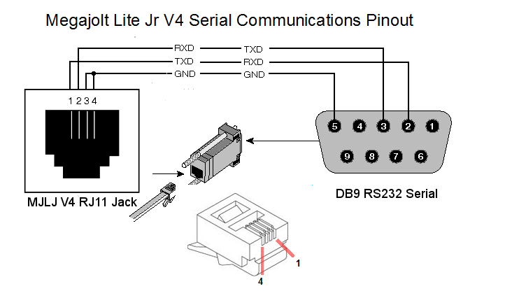
Be careful to wire the actual pin number for your DB9 connector- a common mistake is to forget the pins are in reverse when soldering from the back of the connector.
Verifying Connectivity
After setting the COM port, connect the serial cable to the MJLJ and apply power. If you already have the MJLJ wired into your engine's wiring harness, turn the ignition key to 'on'. If you are testing the MJLJ on the bench, you can simply power the unit with a 9V battery or a suitable 9-15V power supply.
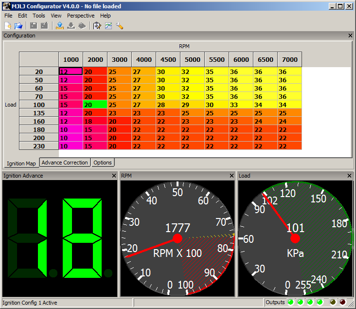
The first way to verify connectivity is to observe runtime data on the screen. On a running engine you'll see the real-time RPM, load and ignition advance values on the gauges at the bottom of the window.
If you're testing on the bench or on a non-running engine, you will still be able to observe some runtime activity by simulating load changing on the engine. For TPS- move the accelerator pedal; MAP- you can manually apply pressure or vacuum to the port on the enclosure.
Common connection problems
If the Configuration Software cannot connect to the MJLJ, you will see one of the following messages in the status bar:
Timeout reading runtime data
The Configuration Software did not get a response from the MJLJ on the serial port you specified.
- Does the MJLJ have power, and connected to the computer with a standard serial cable or compatible USB-Serial adapter? See our USB-Serial adapter information page for help in selecting a compatible adapter.
Could not open port
The Configuration Software could not access the serial port you specified.
Either:
- The port is invalid: Check Device Manager for the proper serial port.
- Serial port in use: If another program is using the same serial port your computer will block the Configuration software from accessing the serial port. Check that you don't have any other software which may open and use the serial port you're trying to use, such as PDA sync software.
At a glance: Main Screen
Runtime Gauges
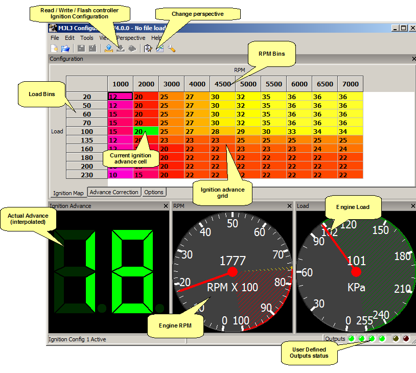
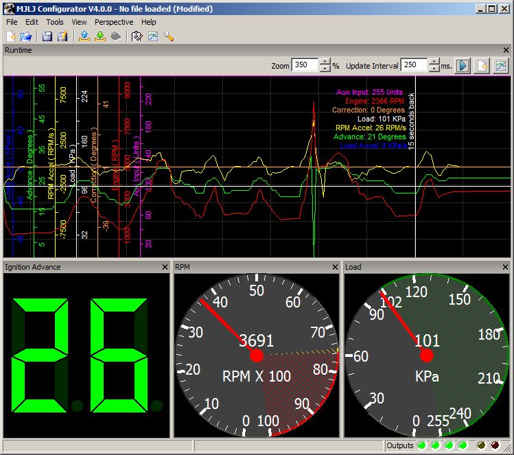
The runtime gauges show the current engine parameters.
Ignition Advance
This is the actual calculated and corrected Ignition Advance and commanded to the EDIS module. This value should correspond to direct measurement of ignition advance, e.g. observation with a timing light.
RPM
This shows the Engine's RPM. The yellow and red regions reflect the current rev limiter setting. The yellow region marks the soft-rev limit region; the red marks when the Hard Rev Limit output is enabled.
Load
The Load gauge shows either KPa or TPS %, depending on your Controller's configuration and Configuration software setting. For MAP sensor based units the scale can be further adjusted to show 0-103 KPa for normally aspirated engines. With forced induction applications the gauge can be set to show the full 0-255KPa range supported by the on-board MAP sensor.
Auxiliary Input
The Auxiliary Input gauge shows the value measured from the Auxiliary input port on the controller. The value measured affects the controller in two ways:
- Advance Correction: The Ignition Advance Correction value is selected from the Advance Correction Table based on the value measured on the Auxiliary Input port.
- User Defined Outputs: The Auxiliary Input value can be used to trigger one or more User Defined Outputs.
The Auxiliary Input can be customized to your preference, under the Auxiliary Input Channel Options
Advance Correction
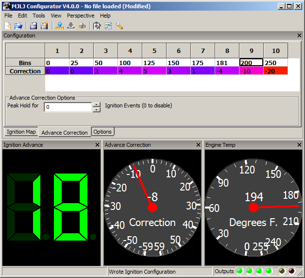
Displays the current Ignition Advance correction value. This correction value represents the value calculated from the Advance Correction table, and ranges from -59 to 59 degrees. This correction value is applied to the value calculated from the main Ignition Advance table.
Configuring Engine Parameters
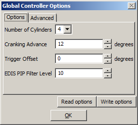
With the controller connected and powered, open the Global Controller Configuration Dialog, located under the "Tools" menu. The global controller settings will be read and displayed in the dialog.
Number of Cylinders
Specify the engine cylinders and the EDIS module you are working with: 4,6 or 8 cylinders.
Cranking Advance
Specify the Ignition advance used during cranking. The controller will use this value when the engine RPM is between 500 and approximately 200 RPM.
- Note: Below 200 RPM, the EDIS module will fire the plugs at 5 to 10 degrees BTDC, regardless of Megajolt cranking advance setting.
Trigger Offset
Use this value to adjust for minor crank sensor misalignments, up to +/-5 degrees of ignition advance.
Note, any value other than zero will limit the ignition map adjustability at the extents of the ignition advance range.
EDIS PIP Filter Level
This configures a software filter in the controller's firmware to minimize the effects of electrical noise on the EDIS PIP line. A larger value makes the filter more aggressive. Usually you will not need to change this.
Updating the Engine Parameters
When you are finished editing the values, Press "Write Options" to send the values to the Ignition controller. The values will be immediately written to Flash memory.
Working with the Ignition Configuration
Retrieving the Ignition Configuration
To read the controller's current configuration, click the toolbar icon ![]() . The current ignition configuration will be read from the MJLJ and displayed in the grid.
. The current ignition configuration will be read from the MJLJ and displayed in the grid.
Ignition Map
The ignition map organized as a 10 x 10 grid of ignition advance values, with Load/RPM bins defining the steps between grid values.
- Load Axis: The Load axis is is represented vertically, from low engine load at the top to high engine load at the bottom.
- RPM Axis: The RPM axis is represented horizontally, from low RPM on the left to high RPM on the right.
- Bins: The steps between engine load and RPM points are defined as 'Bins'- these are the values shown along the borders of the Ignition Map grid.
- Ignition Advance: Each cell in the grid represents an ignition advance value, in actual degrees before top dead center (BTDC).
Editing Ignition Map
Adjusting ignition advance
- Changing single value
To change an ignition advance value, click in the cell you wish to change- the cell will change to editing mode and allow you to change the value.

- Changing multiple cells
To change multiple cells at once, select a region of cells much like you would with a spreadsheet program. You can select contiguous regions by clicking and dragging, or select individual cells cells by holding down the control key while clicking.
Once you've selected the cells you wish to change, right click the selected group. A popup menu will appear, allowing you to set a specific value, increment or decrement the selected cell values.
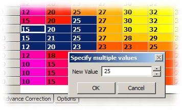
- Ignition Advance range: Allowable ignition advance range is 0 to 59 degrees BTDC.
Adjusting Load / RPM Bins
To change the Load or RPM bins perform one of the following:
- Click the 'Edit' menu and select'Edit RPM and Load bins'
- Ctrl-B in the main window
- Right click on the Load or RPM bins in the grid and select 'Edit RPM and Load Bins'
The Edit Ignition Bin values dialog will appear. Here, you can edit the bin values for the Load and RPM axis.

Edit the values and click 'OK' to confirm your changes.
Advance Correction
The Ignition Advance calculated from the Ignition Map can be further adjusted, or corrected using the Auxiliary Input channel in combination with the Advance Correction table.
Editing Advance Correction Values
- Bins: The Bins determine which Advance Correction value is selected based on the value measured from the Auxiliary Input channel. You can specify a spread of values that suits your preferences, creating coarse or fine regions between bins.
- Correction: The Ignition Advance Correction for the matching Bin. This value can be +/- 59 degrees.
- Peak Hold: Hold the advance correction for X ignition events after a peak value is detected on the Auxiliary Input channel. After the Peak Hold decays, the Advance correction drops down to the correction value for the current Auxiliary Input value. A value of zero disables this feature.
How Megajolt determines ignition advance
- First, Megajolt selects the appropriate RPM and Load bin for the current operating conditions. The ignition advance is selected from the table.
- Then, linear Interpolation smoothing is applied to the Correction value: Should the measured Auxiliary Input value fall between Bins, an intermediate value is calculated from the values specified in the adjacent Bins.
- If the current RPM or Load value falls outside of the map, the advance value is simply railed to value at the respective extents of the map.
- After the advance value is selected, the selected Correction value is applied to the Ignition Advance derived from the main Ignition Map. After correction, the overall ignition advance is limited to 0-59 Degrees Before Top Dead Center (BTDC).
Rev Limit Setting
The rev limit operates independent of the ignition map - when the configured hard rev limit is reached, the hard rev limit output activated, with the automatic soft limit activated 100 RPMs prior to the hard rev limit, setting the ignition advance to 0 degrees.
User Output Configuration
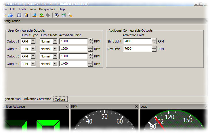
To edit the User Output configuration, click the 'Options' tab below the ignition grid.
User Configurable Outputs
The Megajolt Lite Jr. offers four identical configurable outputs, each with customizable activation.
Output Type
- Load: Select this type to activate on a Load threshold.
- RPM: Select this type to activate on an RPM threshold.
- Auxiliary: Select this type to activate on an Auxiliary Input value threshold.
Output Mode
- Normal: The output will be enabled at or above the set activation point and disabled below set activation point.
- Invert: The output will be disabled at or above the set activation point and enabled below the activation point.
Activation Point
The Activation point sets the threshold for triggering the output.
Hysteresis on outputs
- RPM configured outputs: Hysteresis is set at 100RPMs.
- Load configured outputs: Hysteresis is set at 1 load unit (MAP KPa or TPS %).
- Auxiliary configured outputs: Hysteresis is set at 1 configured Unit.
For wiring instructions on the User Configurable Outputs, see the Installation Guide.
Shift Light
The Shift Light output is activated when engine RPM reaches the configured threshold. Typically this output would be used to illuminate a dashboard-mounted light. For shift light wiring instructions, see the Installation Guide.
Rev Limit
The Rev Limit output is an RPM switch with special behavior.
- At the specified RPM threshold, the Rev Limit output is activated and can be used to trigger an external Rev Limiter module, such as the Autosport Labs Hard Rev Limiter
- 100 RPMs before threshold the ignition advance goes to zero BTDC to act as a 'soft' rev limiter by significantly reducing engine power. Together with an external hard rev limit module this provides an effective rev-limit solution, naturally excluding mechanical over-rev situations.
For instructions on wiring an external rev limit module, see the Installation Guide.
Writing the Ignition Configuration
After editing the ignition map or controller options, you may write the changes to the controller. To do this, click the Write Ignition Configuration toolbar icon ![]() to send your changes to the controller.
to send your changes to the controller.
These changes are made to the Controller's volatile Random Access Memory Memory (RAM), which is used for the actual runtime operation. Therefore, the changes you make will affect the engine's operation. For example, if you are tuning the idle region and you alter ignition advance values in map where the engine is idling, you should observe a change in the engine's behavior once you write the configuration to the controller.
Important Note: Writing the ignition configuration only updates the Controller's RAM.
If changes are not persisted to the controller's Flash memory, the changes will be lost
if the controller loses power (e.g. ignition key turned to 'off').

This behavior is by design. Persisting the data to flash requires a significant amount of time
and momentarily pauses the controller's operation while the Flash memory is written.
Commit to Flash
To make the changes permanent in the Controller's Flash memory, Click the 'Commit configuration to Flash' toolbar icon ![]() . The controller will write the configuration to flash memory, and changes will be preserved across controller power-cycles.
. The controller will write the configuration to flash memory, and changes will be preserved across controller power-cycles.
Additional Options
Load Axis Calibration
If you have a TPS-optioned MJLJ, you can calibrate the Load axis to reflect actual throttle opening percentage.
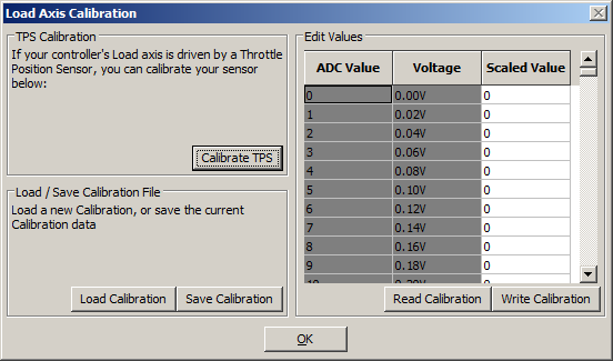
With the MJLJ powered up, click the 'Tools' menu and select 'Load Axis Calibration'. You will see the Load Axis Calibration dialog.
Guided TPS calibration
To calibrate your Throttle Position Sensor, click the 'Calibrate TPS' button on the screen and follow the on-screen prompts.
This guided process reads the closed and open throttle position, generates a new load axis table and Flashes the new table to the controller. Once this is performed, it should not require additional changes unless the throttle linkage or sensor is adjusted or modified.
Advanced Uses
Aside from calibrating a TPS-optioned MJLJ, you can also directly edit the load-axis calibration data. For example, if you're using a non-standard external MAP sensor you can load the sensor's voltage curve using this dialog.
Load / Save calibration
You can load and save the Load axis calibration data using the 'Load Calibration' / 'Save Calibration' buttons. The file is in plain text format of 256 values, with the file's line number representing the ADC voltage (line 0 = 0v; line 255=5.0v; linear scale).
The value on each line maps the ADC voltage to the desired load in KPa or TPS %.
Edit Values
The Load calibration data can be retrieved, inspected and modified directly using 'Read Calibration' / 'Write Calibration' buttons under the 'Edit Values' section.
Auxiliary Input Channel Configuration
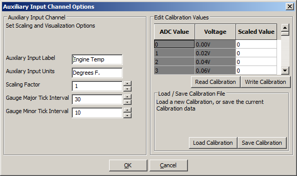
The Auxiliary Input Channel can be configured by accessing the Auxiliary Input Channel dialog under the "Tools / Auxiliary Input Options" menu.
Gauge / Label Customization
- Auxiliary Input Label: Specify a label to match your particular use. Example: "Coolant Temp"
- Auxiliary Input Units: This represents the unit of measurement: Exampe: "Degrees F."
- Scaling Factor: The default scaling factor of 1 gives a input range of 0-255. Adjust the scaling factor to increase the visual range to match your needs.
- Gauge Major Tick Interval / Gauge Minor Tick Interval: These settings adjust the visual appearance of the analog gauge used to display the Auxiliary Input value.
Auxiliary Input Channel Calibration
The Auxiliary input channel maps the Raw Analog-to-Digital (ADC) value measured from the Auxiliary Input port to a more representative value. For example, the raw value can be mapped to temperature degrees if a temperature sensor is connected to the Auxiliary Input port.
Edit calibration values
You can edit the mapping values directly by editing the values in the table. The voltage measured on the port is mapped to the editable Scaled Value field in the table.
The calibration data is read and written directly to flash memory using the respective buttons.
Load / Save calibration
When mapping a sensor or other input, it is usually more efficient to map the values in a spreadsheet or other editing program and import them into the controller. You can load and save the Load axis calibration data using the 'Load Calibration' / 'Save Calibration' buttons. For importing, the file must be in plain text format of 256 values, with the file's line number representing the ADC voltage (line 0 = 0v; line 255=5.0v; linear scale).
GM sensor Calibration File
Calibration file for the GM coolant or IAT sensor: Download
Dual Switchable Ignition Configurations
The Megajolt Lite Jr. supports on-the-fly switching between two Ignition Configurations. Each independent configuration includes the entire ignition map and all controller options (Engine type, User-defined outputs, Rev limit and Shift light settings).
Enable hardware switch
Switching between ignition configurations requires wiring the option switch to the Controller. Refer to the Installation Guide for more information.
Configuration software behavior
Once enabled in the controller, the software will alert you when the controller switches to a different ignition configuration. You can define how the software reacts to the switch:
- No Action: The software only alerts you of the change.
- Prompt to read configuration: The software prompts you to read the Ignition Configuration the controller was just switched to.
- Auto-Read configuration: The software automatically reads the Ignition Configuration the controller was just switched to, discarding any in-progress changes made in the software.
Important Usage Notes
The switchable Ignition Configurations can be thought of two controllers in one; or, one controller with two different personalities.
This means you must manage the two Ignition configurations independently by separately reading, writing and flashing the Ignition Configuration as appropriate.
Tuning your Ignition Controller
Charting / Runtime view
You can monitor the runtime operation of the engine, plotted over time by selecting the Charting/Runtime view.
Tuning Perspective
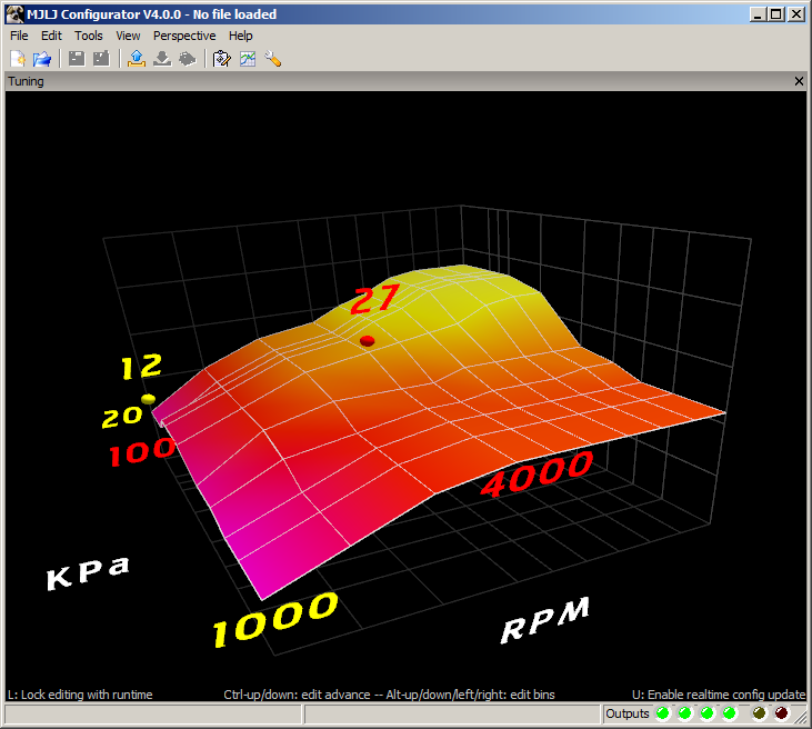
The configuration software offers a 3D interactive editor which makes it easy to tune the ignition map and Load / RPM bins while the engine is running.
In this view you will see a contour plot of the ignition map, with the ignition advance as the elevation of the surface. 'Hot' colors indicate more advance, and 'cool' colors indicate less.
You will see two bouncing balls:
- Red Ball: The red ball indicates the closest run-time cell the controller is using for the ignition advance; this will move around as the engine RPM and load changes.
- Yellow Ball: The yellow ball indicates your current editing point.
Editing the Ignition Map
- Navigation: Use the arrow keys to move the editing point around the Ignition Map.
- Increase/Decrease advance: To increase advance at the editing point, hold down the ctrl-key and press the up arrow key. Conversely, to decrease the ignition advance, hold down the ctrl-key and press the down arrow.
- Modify Load/RPM bins: You can increase/decrease the selected RPM bin by pressing Alt-left arrow / Alt-right arrow. Correspondingly, the selected Load bin can be modified by pressing Alt-up arrow / Alt-down arrow.
Hot Keys
- Lock editing with runtime: Pressing 'L' on the keyboard toggles locking the editing point (yellow ball) with the runtime point(red ball), making it easier to edit the map in the region where the engine is running.
- Enable real-time config update: Pressing 'U' on the keyboard toggles real-time updating of the edited ignition point. The values are stored in the Controller's RAM, but not persisted to flash.
Visualization
You can rotate, pan and zoom the 3D tuning view to match your preferences:
- Rotate: Click and drag the map to rotate the Ignition Map in 3D
- Pan: Hold Shift + click and drag to Pan the Ignition map
- Zoom: Hold Alt + click and drag to zoom the Ignition map
Data logging
The MJLJ Configuration software provides the ability to log runtime data to a file for later analysis.
Starting a Data logging Session
To start a Data Logging session, click the menu 'File' and select 'Start Datalog'. You will be prompted to supply the filename of the Data logging file.
Quick Data Logging
You can start a quick Data Logging session by clicking the Menu 'File' and selecting 'Quick Datalog' - or press F5 in the main window.
The file will be automatically created in the last selected directory with the automatically generated file name "MJLJ_Log_<DateTime>.csv" For example, "2007-11-26_19.57.02.csv"
If you select 'Quick Datalog' while a Data Logging session is active, the current file will be closed and a new file started.
Mark Datalog
To mark a noteworthy event while a Data Logging session is active, click the Menu 'File' and select 'Mark Datalog' - or press Space Bar
Stop Logging
To stop logging, select the menu item 'File' and select 'Stop Datalog' - or press ESC in the main window.
Open Datalog
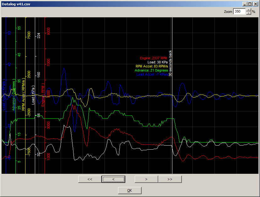
You can view a previous Datalog by clicking the Menu 'File' and selecting 'Open Datalog'.
Browse to the file and click 'Open'. The Datalog will be shown in a popup window.
- Zoom Use this to zoom in and out of your Datalog file.
- Navigation The forward/reverse buttons adjusts the view 10 seconds forward or backwards in time. The Fast forward/reverse buttons adjust the view 60 seconds.
Logfile Format
The contents of the log file is stored in a plain-text CSV format. You can read this file with a standard text editor or a spreadsheet program like OpenOffice Calc or Microsoft Excel.
- Timestamp: The time of the log file entry
- RPM: Engine RPM
- Load: Engine Load, in KPa or TPS %
- Advance: Actual Ignition Advance in degrees BTDC
- RPM_Accel: RPM Acceleration, in RPM/sec
- Load_Accel: Load Acceleration, in KPa/sec or TPS/sec
- Aux Input: Auxiliary Input value. This header value will change based on the configured label under "Advance Correction" preferences.
- Advance_Correction Advance Correction value calculated from the Advance Correction table.
- Mark_interval: Indicates a marked portion of the log data. 1 = Marked.

